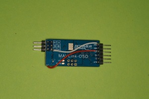
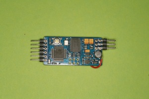
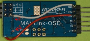
This post will be dedicated to explain a really simple but very effective method to make the RcTimer Minimosd run on 5V for both the digital and analog side of the board. Some other very important information about the RcTimer MinimOSD can be found at this rcgroups topic. I highly recommend you to read the section that’s talking about how to hook up the supplied 4pin header! Even better: buy the 6pin header as recommended in that post!
First let me start with a little introduction of the MinimOSD and why you should do this mod.
What is MinimOSD?
MinimOSD is an OSD (on-screen display) originally designed by 3DRobotics. The MinimOSD can be hooked up to a APM (ardupilot Mega) flightcontroller and with some other firmware it’s possible to hook it up to a MultiWii based flight controller. The OSD projects all sorts of flight information on your FPV image: speed, altitude, angle of attack, distance to home, etc etc. The original MinimOSD can be found here. The MinimOSD is produced by A LOT of other vendors at the moment, for prices as low as $ 10,-
A small demonstration of the MinimOSD running RushOSD firmware:
A little explanation about the MinimOSD
The MinimOSD works like this: It consists of two parts on the board. A digital side running on 5V with the atmel microprocessor to facilitate the communication between the Flight Controller and the MinimOSD. The other side of the board is the analog side, standard running on 5V – 12V and consists of the MAX7456 chip (responsible for the overlay on your image) and a voltage regulation circuit. The digital side will be sending the digital data from the flightcontroller to the analog side (the maxim chip) and the analog side will overlay the data.
Why you should mod the RcTimer MinimOSD
A lot of people have fried their MinimOSD in the past. The regular way to power the MinimOSD is with the 5V from the Flight Controller for the digital side and 5 – 12V from the Video TX to the analog side, this can be both with a 1 and 2 Lipo set-up. The problem with this standard way of hooking the thing up is dat due to differences in GND the Maxim OSD chip is prone to burn out. A much better way is connect both the digital and analog side of the MinimOSD to the 5V from the Flight Controller. This way the Maxim chip will survive! Another reason to do the mod is when you’re using a LRS (Long Range systems) operating on UHF (433Mhz). It is known that the switching regulator on the analog side of the MinimOSD (normally responsible for reducing the analog voltage to 5V) is making noise on 433Mhz, wich will reduce the range of your RC link.
How to do the mod
Since the RcTimer MinimOSD lacks the solderpads to connect the digital and analog side as seen on the original 3D Robotics MinimOSD you will need to do some really simple mods.
Start off by getting some small gauge wire you’ ve laying around. Lay the MinimOSD down on his front.
1. Take the wire and solder it on the +5V pin at the digital side. Make sure the wire isn’t connected to any other pin then the +5V!
2. Take another wire and solder it to GND on the digital side. Again make sure the wire isn’t connected to any other pin then the GND!
3. Solder the other side of the GND wire to the analog GND IN pin at the digital side.
Now turn the MinimOSD. We only have some minor and easy work to do.
4. Solder the +5V wire to the component on the analog side as shown in the picture below. This way we’re bypassing the switching regulator and feeding the 5V from the digital side, coming out of your flight controller, directly to the maxim OSD chip. (remember what I told above? The switching regulator will make noise on the 433Mhz (UHF) band what will decrease your UHF range!)
At this moment do NOT connect a 12V battery anymore to the analog side! You will destroy your MinimOSD! We’re going to solve this at step 6
6. In order to use the pins on the MinimOSD’s analog side as a pass through for the + between your video transmitter and camera, we will have to cut the trace that’s running from the + pin to the regulator circuit. Use a exacto knive and make a cut at the trace as seen on the following picture. You can cut the trace at point A or point B, whatever you like. Make sure that you check afterwards with a multi-meter that the connection is really gone! If you did it wrong and didn’t interrupt the connection you WILL release some magic smoke from the MinimOSD when you plug the 12V in. So again: MAKE SURE THE CONNECTION IS GONE!
Allright! You’re done! That’s all. Simple huh? Now it’s time to flash the firmware and add it to your flight controller and camera/video transmitter.
I use two servo plugs to hook up the camera and video transmitter to the MinimOSD. This way the video signal, 12V and GND will run from my video transmitter to the MinimOSD. The 12V will never enter the circuits but only be connected to the “12V out” pin to give my camera the 12V. The GND from the camera and the vTX will make a common ground with the digital ground. The Video signal will be fed into the Maxim chip, get some data overlay, and then will be redirected to my video TX.
I will publish some pictures soon how everything is hooked up. I will also write a small guide how to upload the RushOSD firmware for use with MultiWii.
Update: Check out my new follow-up post howto apply a heatsink to your MinimOSD!
Questions?
Do you have any questions? Don’t be shy, just post a message below the article. I will try to answer them asap!


[…] RcTimer MinimOSD 5V mod […]
Perfect…exactly what I was looking for! Looking forward to seeing how you hooked everything together.
Hi deadlyda!
Thanks for the nice feedback. Last weekend I’ve put everything together and did some test flights with my 450 quad, everything works great! Will make some pictures soon (and some drawings) how to connect everything. It really is very simple: use two servo wires to connect your transmitter and your camera to the MinimOSD (based on your setup and transmitter: signal, + and ground). Connect the MinimOSD to the MultiWii and you’re good to go!
Have fun flying!
Got an “off topic” question:
I did the mod as per instructions, and it seems to be fine. However I’m having a major problem trying to flash updated firmware. I keep getting a “avrdude: stk500_getsync(): not in sync: resp=0x00” message.
I’ve seen other people with the problem, but after much searching, I have yet to find a fix.
I’ve tried replacing drivers, tried different computers…and am starting to think that I have a bad FTDI.
What do you use to flash the MAVLink?
Hi! This is a error you’ll get when your computer isn’t communicating with the arduino (in this case MAVLink OSD). It could be a bad FTDI. Are you sure you’re selecting the right arduino type and communication port?
btw: i’m using arduino 1.0
Yeah…I’ve tried multiple computers, got a 2nd FTDI cable, double & triple checked all the settings, etc, etc. I just read on a completely unrelated topic that using a USB3 port instead of USB2 can cause some serial coms programs to fail.
I’ll try usingUSB2 this weekend, and see if that works.
That’s true indeed. But you said you’ve tried several computers…I can’t imagine that all those computers had an usb3.0 port…
Actually, yes they do. All my machines have at least one USB3 port, as well as the old USB2. By happenstance, I have only used USB3 so far.
I’ll be giving USB2 a try this weekend.
Hi,
I have a 5v camera and 5v input into transmitter. What would be the best was to do this?
I was thinking since it’s a 5v sysem with camera to transmitter I could do similar above but power from transmitter 5v to both sides, correct? If I’m right, could you explain it to me better in detail on how to do?? please :O)
Hi Erik,
I’m so sorry I forgot to reply to your message. Did you already worked it out?
Thank you so much for this!! Worked perfectly… I was regretting buying the knock off… You saved Me!
Awesome to hear that! Enjoy your minimosd….it rules!
[…] posts aangemaakt! Scheelt weer dubbelwerk, zo helpen we elkaar allemaal weer wat verder. hier: RcTimer MinimOSD 5V mod | Hoogvlieger staat ook nog wat algemene informatie over minimosd / rushosd in het begin. Staat heel beknopt de […]
My mavlink-osd v2.0 looks slightly different.
I found the trace that needs to be severed, but i have no idea on what side i should route the 5v cable to the “330”
http://postimg.org/image/nr59dbwyh/
Hi Hoogvlieger, nice info, I got my osd for my zmr250 quad, and its running hot, am planning to do both these mods, but have a question, i got the osd from http://multirotormania.com/osd/383-minimosd.html?search_query=osd&results=16 and am using the 5Gz rx system do i needed to by pass the swithcing regulator? or i can directly connect the 5v from digital to analog ?
And if i have to by pass, how to mod this board ?
Hi Merin,
The version of the minimosd you are referring to is not the version like the RCtimer one.
I think your version will have two solder pads on the bottom that you can solder together to power both the analog and digital part from the 5V. If you do it like that, be sure to not hook up any 12V.
thanks maarten112, yes i tried that and it works, but i did hookup the +12V on other side once, because the manual dint mention any thing NOT to do that.. but after reading forums i removed the 12V, and it survived 🙂 (lucky me)
I am using a Fatshark 5V camera with a 12V input on the Fatshark, outgoing 5V to the camera with the video lead cable (as I am sure you are familiar with this set up). How would I connect the Minim OSD in that case? Just the In & Out Pins + Ground, and leave the 5V feed from the transmitter to the camera? Tks for your help on this one, I am really not sure how to integrate my Crius MavLink to this setup… All OK for Naze32 side, I am clear, but not for the overlay power and signal!? Thanks for your support on this one please. Regards
Hi Frederic!
Yes! You are totally right about what you’re saying. Just don’t connect the 5V from the transmitter to your MinimOSD. Your Crius will be able to power both the digital and analog side of the minimosd!